绘制流水线
绘制流水线的功能是在给定3D场景和指定观察方向的虚拟摄像机的几何描述时,创建一幅2D图像
学习目标
- 了解在Direct3D中如何表示3D物体
- 学习如何建立虚拟摄像机的模型
- 理解绘制流水线——由3D场景的几何描述生成2D图像的过程
2.1 模型表示
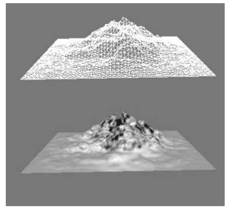
任何物体都可以用三角形网格逼近表示。三角形网格是构建物体模型的基本单元
描述三角形单元时,我们需要指定该三角形单元3个顶点的位置。而描述物体时,我们需要指定构成该物体的三角形单元列表。
2.1.1 顶点格式
在Direct3D中,顶点除了包括空间信息外,还可以包括其他的附加属性。
在下面的例子中,创建了两个顶点格式:第一种包括位置和颜色属性,第二种包括位置、法线和纹理坐标
1
2
3
4
5
6
7
8
9
10
11
struct ColorVertex
{
float _x, _y, _z; // position
DWORD _color;
};
struct NormalTexVertex
{
float _x, _y, _z; // position
float _nx, _ny, _nz; // normal vector
float _u, _v; // texture coordinates
};
顶点结构定义好之后,就需要使用灵活顶点格式(FVF)标记的组合来描述顶点的组织结构
#define FVF_COLOR (D3DFVF_XYZ | D3DFVF_DIFFUSE)
该宏定义包含了位置属性和漫反射颜色属性
#define FVF_NORMAL_TEX (D3DFVF_XYZ | D3DFVF_NORMAL | D3DFVF_TEX1)
该宏定义包含了位置、法线以及纹理坐标等属性
FVF标记的指定顺序必须与顶点结构种相应类型数据定义的顺序保持一致
2.1.2 三角形单元
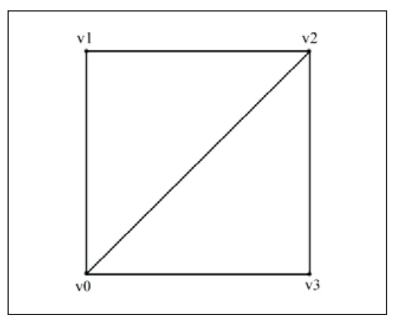
例如,为了构建一个矩形,我们将其分解为两个三角形单元,并指定每个三角形单元的顶点
1
2
Vertex rect[6] = {v0, v1, v2, // triangle0
v0, v2, v3}; // triangle1
注意 三角形各顶点的指定顺序非常重要,我们称其为绕序(winding order)
2.1.3 索引
顶点列表包含了全部独立顶点
1
Vertex vertexList[4] = {v0, v1, v2, v3};
索引列表包含了指向顶点列表的索引
1
2
WORD indexList[6] = {0, 1, 2, // triangle0
0, 2, 3}; // triangle1
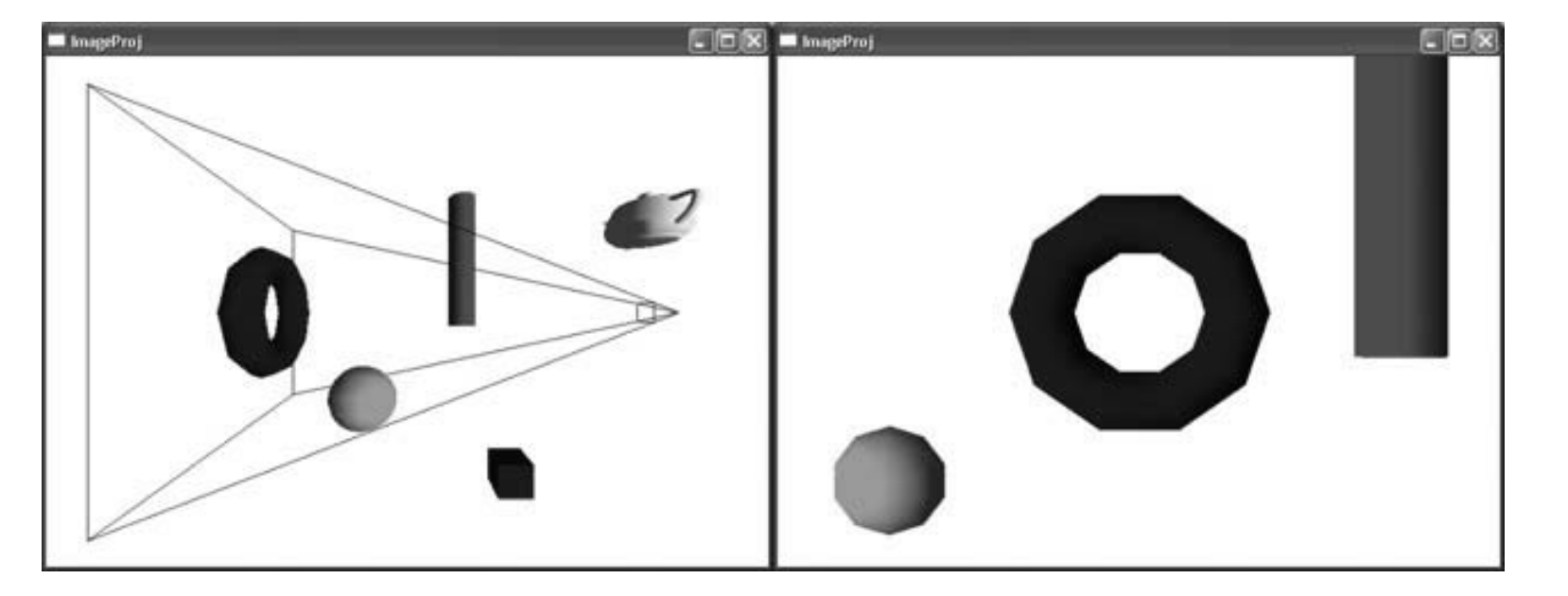
2.2 虚拟摄像机
摄像机指定了场景对观察者的可见部分,即我们将依据哪部分3D场景来创建2D图像
在世界坐标系中,摄像机有了一定的位置和方向,定义了可见的空间体积
2.3 绘制流水线
一旦建立了3D场景的几何描述,并设置好虚拟摄像机,下面的任务就是在显示器中建立该场景的2D表示。为实现这一目标所必须实施的一系列运算被称为绘制流水线
以下是绘制流水线的大致流程
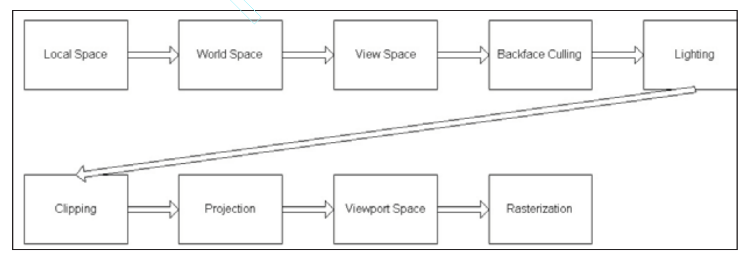
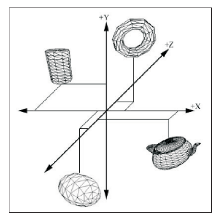
2.3.1 局部坐标系
局部坐标系,是用于定义构成物体的三角形单元列表的坐标系。采用局部坐标系的优势体现在它可以简化建模过程。在物体的局部坐标系中建模要比直接在世界坐标系中容易得多。
2.3.2 世界坐标系
位于局部坐标系中的物体通过一个世界变换的运算变换到世界坐标系,包括平移、旋转、比例运算,分别用于设定该物体在世界坐标系中的位置、方向以及模型的大小
世界变换用一个矩阵表示,并由Direct3D通过IDirect3DDevice9::SetTransform方法来加以应用
1
2
3
4
5
6
7
8
9
10
11
12
13
14
15
// Build the cube world matrix that only consists of a translation.
D3DXMATRIX cubeWorldMatrix;
D3DXMatrixTranslation(&cubeWorldMatrix, -3.0f, 2.0f, 6.0f);
// Build the sphere world matrix that only consists of a translation.
D3DXMATRIX sphereWorldMatrix;
D3DXMatrixTranslation(&sphereWorldMatrix, 5.0f, 0.0f, -2.0f);
// Set the cube’s transformation
Device->SetTransform(D3DTS_WORLD, &cubeWorldMatrix);
drawCube(); // draw the cube
// Now since the sphere uses a different world transformation, we
// must change the world transformation to the sphere’s. If we
// don’t change this, the sphere would be drawn using the previously
// set world matrix – the cube’s.
Device->SetTransform(D3DTS_WORLD, &sphereWorldMatrix);
drawSphere(); // draw the sphere
2.3.3 观察坐标系
2.3.4 背面消隐
每个多边形都有两个侧面,其中一个侧面标记为正面,一个侧面标记为背面。通常,背面是不可见的
如果默认的消隐方式不能满足应用的要求,可以修改D3DRS_CULLMODE来达到目的
1
Device->SetRenderState(D3DRS_CULLMODE, Value);
其中,value可取以下值:
- D3DCULL_NONE 完全禁用背面消隐
- D3DCULL_CW 只对顺时针绕序的三角形单元进行消隐
- D3DCULL_CCW 默认值,只对逆时针绕序的三角形单元进行消隐
2.3.5 光照
2.3.6 裁剪
将那些位于视域体外的几何体剔除掉
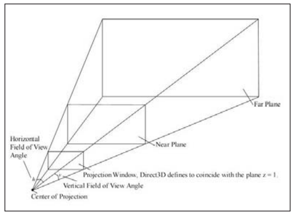
2.3.7 投影
观察坐标系中,我们的任务是获取3D场景的2D表示。从$n$维变换为$n-1$维的过程称为投影
透视投影会产生近大远小的视觉效果,可使我们可以用2D图像表示3D场景
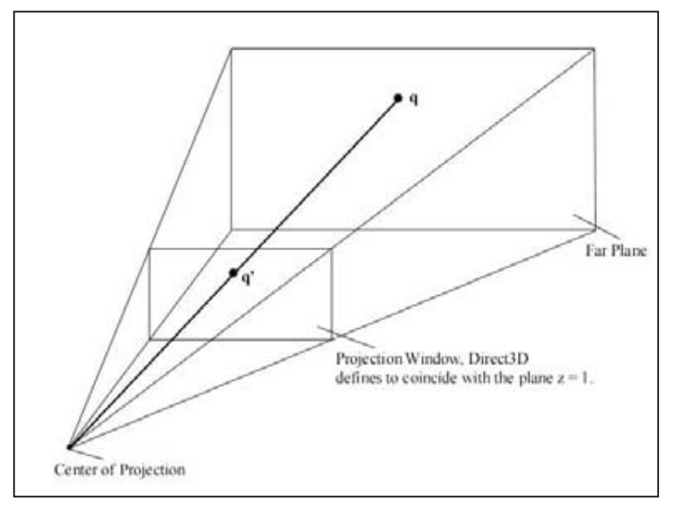
投影变换定义了视域体,并负责将视域体中的几何体投影到投影窗口中
2.3.8 视口变换
视口变换的任务使将顶点坐标从投影窗口转换到屏幕的一个矩形区域中,该矩形区域被称为视口
2.3.9 光栅化
顶点坐标变换为屏幕坐标后,就有了一个2D三角形单元的列表。光栅化的任务是绘制每个三角形单元,如何计算构成三角形单元的每个像素的颜色值
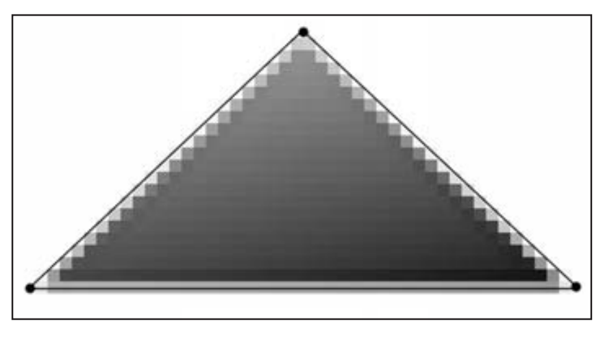
光栅化的最终结果是显示在屏幕上的一幅2D图像
2.4 小结
- 3D objects are represented as triangle meshes—a list of triangles that approximates the shape and contours of the object.
- The virtual camera is modeled as a frustum. The volume of space inside the frustum is what the camera “sees.”
- 3D objects are defined in local space and are then all brought into one world space system. To facilitate projection, culling, and other operations, the objects are then transformed to view space, where the camera is positioned at the origin and looking down the positive z-axis. Once in view space, the objects are projected to the projection window. The viewport transformation transforms the geometry on the projection window to the viewport. Finally, the rasterization stage computes the individual pixel colors of the final 2D image.
总结
这一章学习了创建和绘制场景的概念,学的有一点迷糊,下面的部分不是很重要就没有学明白:
- 观察坐标系
- 投影
- 视口变换